The technically correct use of thermocouples and oxygen probes is remarkably simple. However, errors can often creep in. We’d be happy to help you identify and correct them.
On this page, you'll find a collection of information on working with thermo-control sensors. This includes:
We for our thermocouples and oxygen probes. Purchased parts and consumables are excluded from this warranty and are subject to the respective statutory warranty periods.
Statutory obligations remain unaffected by the above warranty.
Thermocouples
Unless otherwise explicitly stated, the is valid for and covers all manufacturing defects, such as leaks, display malfunctions, thermowire breakage, or drift.
This warranty expires as soon as at least one of the following conditions applies:
At least one of the ceramic tubes has been damaged mechanically or chemically
The product was not manufactured by thermo-control, repaired by a third party, or structurally modified.
The thermocouple was used continuously at temperatures above 1,400 °C (Type B: 1,600 °C).
Upon request, thermo-control can perform an on-site comparison measurement before the warranty period expires. If an undamaged thermocouple shows a deviation of more than 0.5% of the temperature being measured, we will replace it with a new one.
Oxygen probes
The warranty period is up to 4 years and depends on the application.
(Leakage)
Every vacuum thermocouple undergoes a 100% helium leak test, the results of which are documented in the manufacturer's certificate.
If a leak is detected in the thermocouple, it is usually a sign that at least one ceramic tube has broken.
Furnace gases can enter the thermocouple through the break in the ceramic tube and corrode the measuring wires. The vacuum further exacerbates this effect. This results in inaccurate measurements, which can lead to incorrect heat treatment.
To ensure this defect can be corrected in a timely manner, the design is such that the thermocouple loses its seal in the event of a break. A sufficient seal will remain intact so that, for example, the graphite heating blocks are not damaged when the furnace is started up. However, the leak is significant enough that the high vacuum required for production cannot be achieved. This prevents improper heat treatment, ensuring your batch remains intact!
Thanks to this design feature, the operator can correct the error in a timely manner and remove the broken thermocouple. The thermocouple should then be sent in for repair.
If the thermocouple is removed immediately after it is damaged, there is also a good chance that the expensive measurement wires can be reused through a .
Delivery Times
All thermocouples and oxygen probes we supply are manufactured to order. Provided the individual parts are in stock, delivery times are as follows:
thermo-control Thermocouples 2–3 business days
thermo-control oxygen probes: 4–5 business days
Prices are ex works () provided the materials are in stock. The binding delivery date will be provided with the order confirmation.
Serial Number
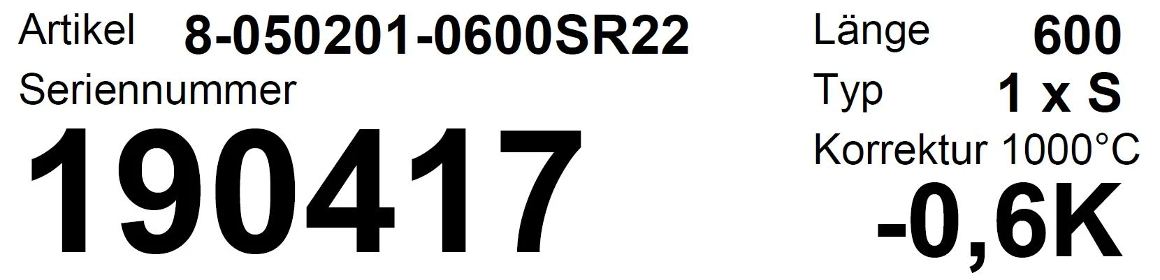
All products shipped with a certificate are assigned a serial number. The serial number is structured as follows:
DD MM xx
JJspecifies the year of manufacture
MMthe month of manufacture
xxSequential numbering of the manufactured product for that month
All production-related data, such as the lot number of the thermal wire used, is linked to the serial number in our ERP system.
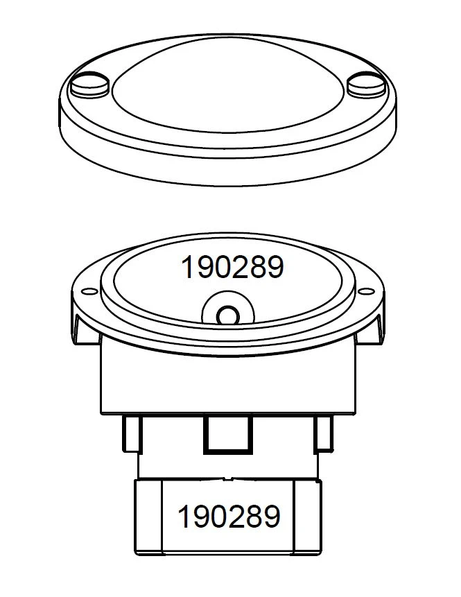
The serial number is printed on the product label. For products with connector heads, the serial number is also written inside the connector head with a felt-tip pen. This has often proven useful when the label has worn off after years of use.
Process Connections
Accurate measurement of temperature or oxygen content often requires precise placement of the sensor. If the measurement is not taken manually, process connections are often used. These ensure that the measurement is always taken at the same location. This is especially true when measurements must be taken in fluids.
pipe thread
Given our background in installation technology, inch-sized pipe threads are also selected as process connections. In such cases, cylindrical internal threads are often used on the process side, and tapered threads on the sensors. This is intended to ensure that the connection is automatically sealed.
Tapered threads are defined in DIN 10226.
Common types of straight pipe threads according to DIN 228.
Implementation
Outer Diameter
Flange Diameter
Gradient
G3/8
16.6 mm
14.95 mm
1.34
G1/2
20.96 mm
18.63 mm
1.81
G3/4
26.44 mm
24.12 mm
1.81
G1
33.25 mm
30.29 mm
2.31
Small flange per ISO 2861
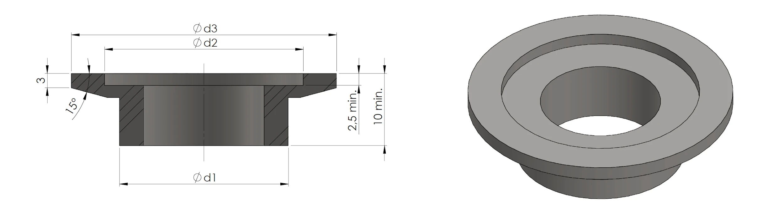
This international standard specifies the dimensions of quick-release couplings of the clamping type, as used in vacuum technology. It also covers O-rings and their holders, which are connected to these couplings to ensure vacuum tightness.
DN
Maximum Nozzle Diameter Ød1 [mm]
Inner Ring Diameter Ød2 [mm]
Outer Diameter Ød3 [mm]
16
20
17,2
30
25
28
26,2
40
40
44,5
41,2
55
Compression Fitting
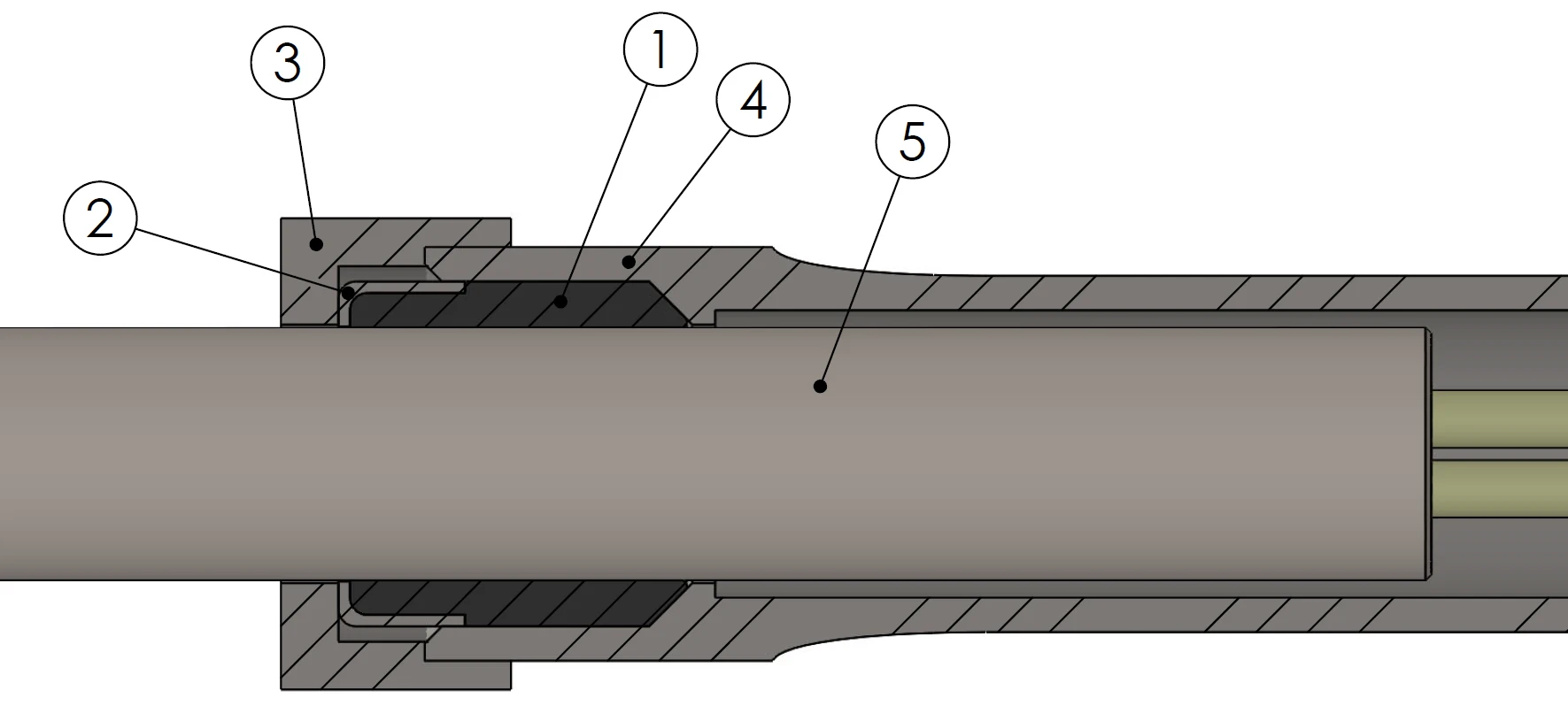
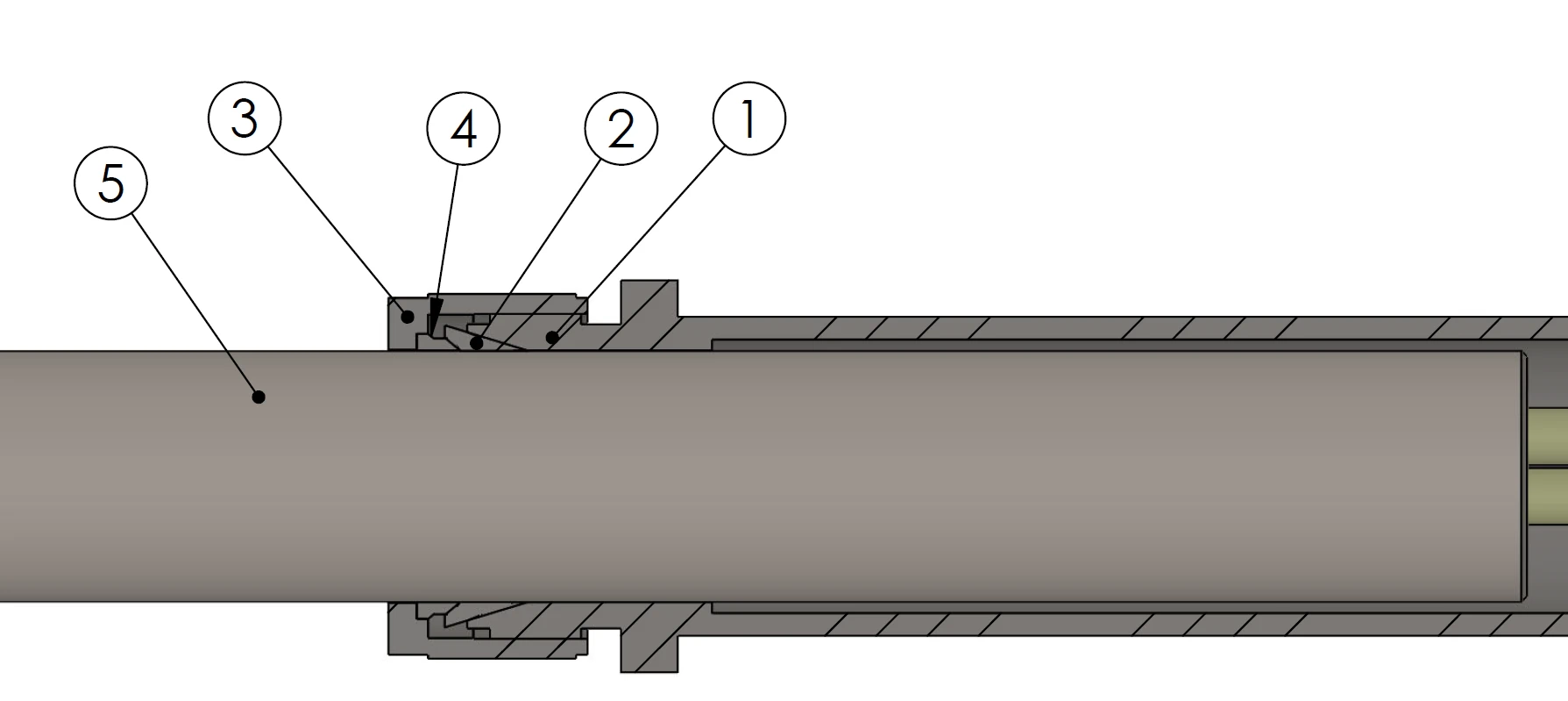
Similar to the compression fittings manufactured by Dresser Couplings Ltd., these feature a sealing ring that is pressed into a cone using a cap. Unlike cutting-ring fittings, this allows for precise positioning of the sensor without damaging the support tube.
However, installation in accordance with the specifications is essential here, as otherwise the sensor could be forced out of the chamber under high pressure. This poses a high risk to people and the equipment. The cap prevents the rubber of the O-ring from being damaged inside the nut. This results in a longer service life.
Schematic diagram of a compression fitting:
Sealing Ring
Cap
Tension nut
Nipple
Support Tube
Compression Fitting
Made famous by Swagelok, cutting-ring fittings are characterized by their ability to withstand very high pressure. The cutting rings can be loosened with a little effort. If this is done without causing damage, they can be reused. The notches on the retaining tube are minimal but visible.
Schematic diagram of a cutting ring fitting:
Nipple
Lower cutting ring
Mother
Upper cutting ring
Support Tube
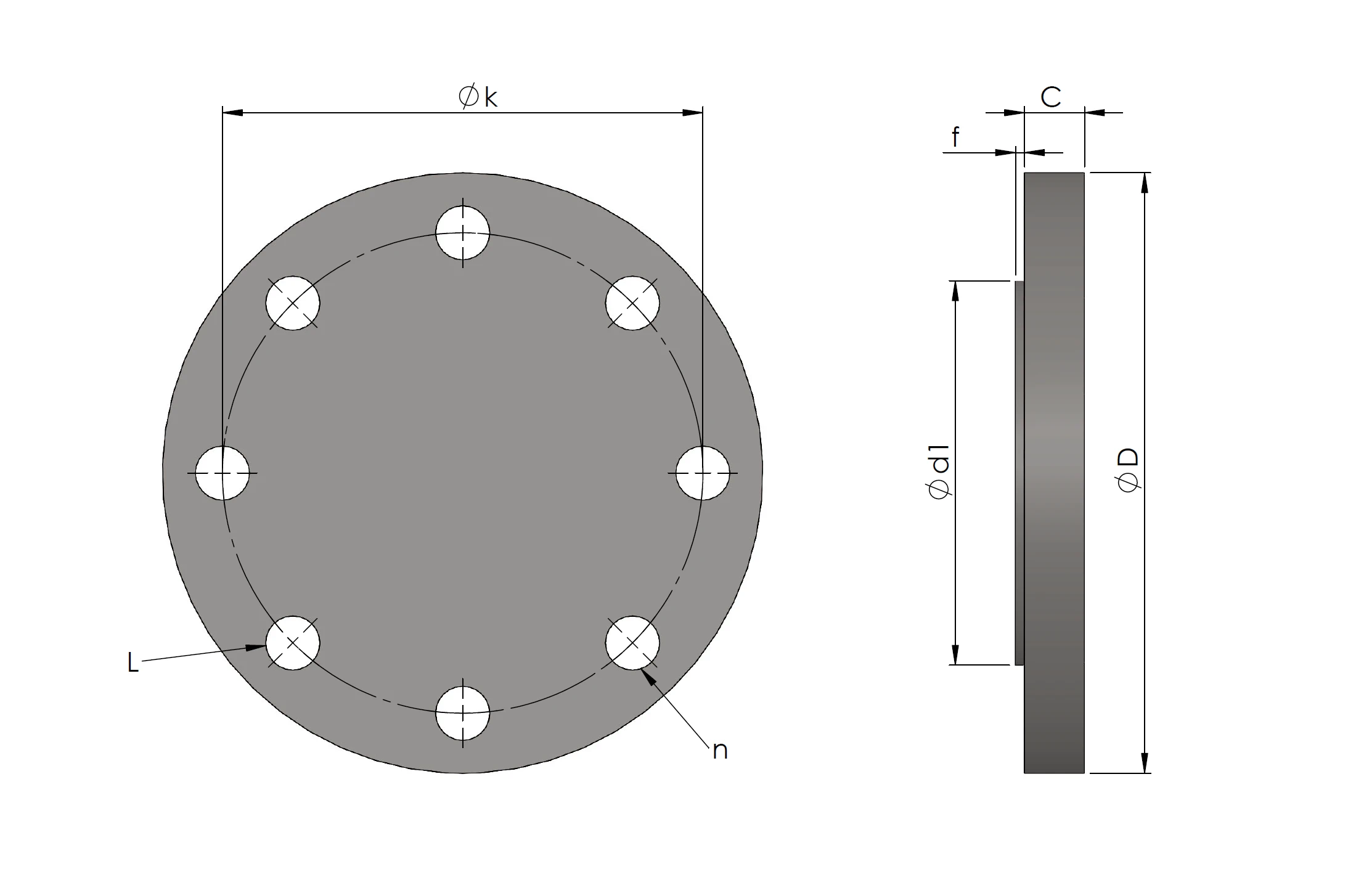
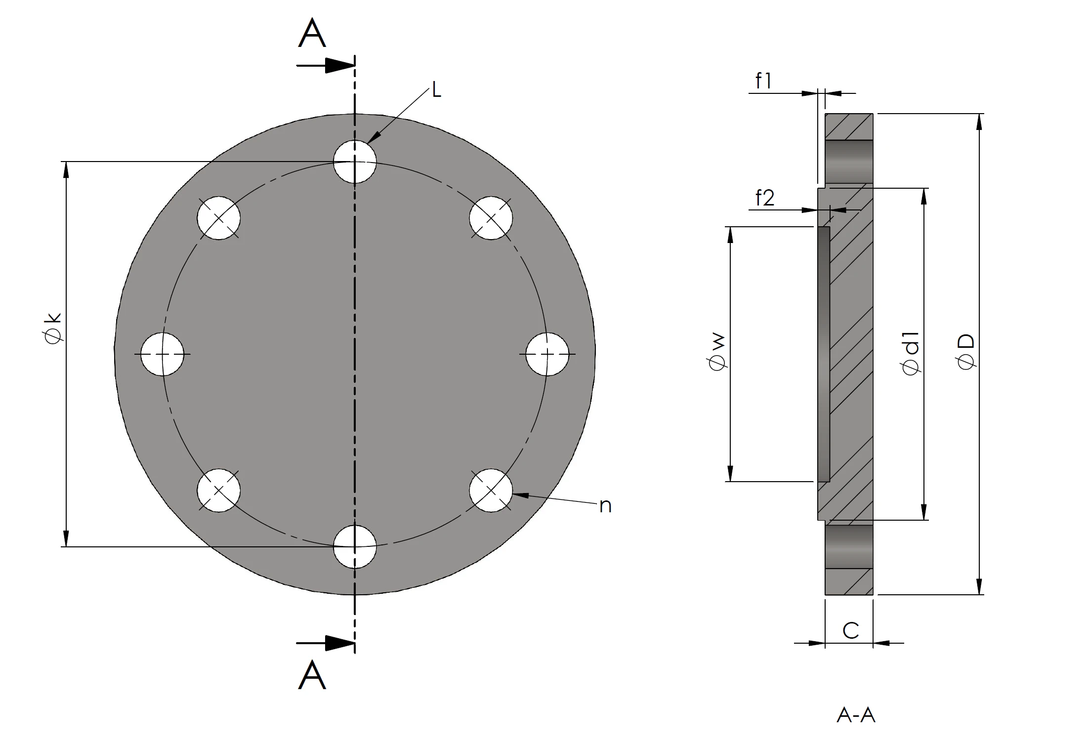
Flange in accordance with DIN EN 1092
We use Type 5 blind flanges in PN16 and PN25 versions as the base body. Commonly used nominal diameters are DN25, DN40, and DN80. The sealing surfaces are designed according to customer specifications. Shapes B and G are listed as examples. For other designs, please contact us at