Accessories / Consumables
We offer a variety of accessories and consumables for our products. This includes standard components such as connectors or cables. However, production according to customer requirements is also possible. Therefore, we look forward to your inquiry.

Thermocouples
We offer the following accessories for thermocouples:
Connectors
According to DIN EN 50212, thermal plugs for thermocouples are divided into two types. Form A, commonly referred to as the standard, is the larger and is fitted with round pins. Form B, commonly miniature or mini, is fitted with flat pins. The number of pins is two or three.
The materials of the pins correspond to the tensile composition of the corresponding compensation materials from DIN EN 60584-3.
Thermocouple | Material pairs | |
---|---|---|
+ | – | |
T | Copper | Copper-Nickel |
J | Ferrum | Copper-Nickel |
E | Nickel-Chrome | Copper-Nickel |
K | Nickel-Chrome | Nickellegierung |
S | Copper | Copper alloy |
R | Copper | Copper alloy |
B | Copper | Copper |
N | Nickel-Chrome-Silizium | Nickel-Silizium |
Thermal plugs are available in 4 different versions:
Economy
Inexpensive design with fiber reinforced nylon body and hollow pins on Form A connectors. They are designed for a permanent load of 190°C. The connections are equipped with simple screws.
Standard
Version with fiber-reinforced thermoplastic body and solid pins on Form A plugs. They are designed for a permanent load of 230°C. The connections are equipped with clamping plates for easy assembly.
High temperature
Version with fiber-reinforced thermoplastic body and solid pins on Form A plugs. They are designed for a permanent load of 350°C. The connections are equipped with clamping plates for easy assembly.
Ceramic
Version with ceramic/porcelain body and solid pins on Form A plugs. They are designed for a permanent load of 650°C. The connections are equipped with clamping plates for easy assembly.
Cables
General
The voltage of the thermocouples is defined towards the zero point. Therefore, thermocouples must not be connected to a normal copper power line. This would lead to measurement errors. Consequently, special leads must be used for thermocouples. These are usually called compensating lines.
Their thermal voltage is identical to that of the connected thermocouple up to ~200°C. For areas above 200°C, the original alloys of the thermocouples should be used as far as possible.
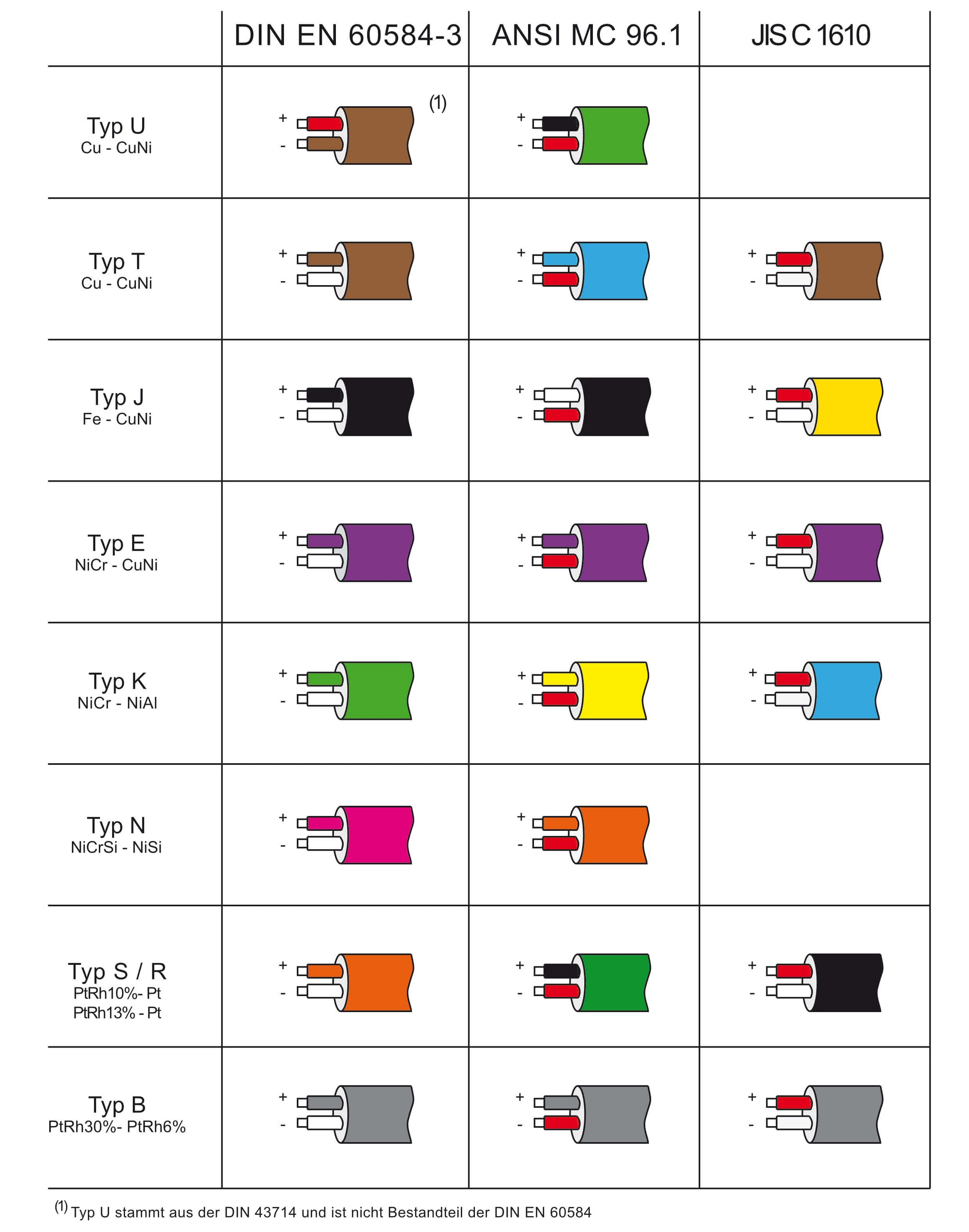
It is important to know that the materials of the cables, as with the thermocouple, are different. Therefore, the correct polarity must be observed. For convenience, the insulation layers are made in the colors of the thermocouples.
Specifications
Thanks to modern electronics, the resistance of the cable and the cross-section requirements are practically non-existent. Common cross-sections are 0.22mm² or 0.5mm².
The construction of the insulation follows the local circumstances. Hence, there is a very high variety of designs. Four common materials are:
PVC
This is relatively cheap, flexible and is used up to ~100°C.
Silicone
Compared to PVC, this material is slightly more expensive, but has much higher flexibility and temperature resistance up to ~180°C.
Polytetrafluoroethylene (Teflon™)
This material is characterized by a very high-temperature resistance of ~240°C. In addition, it is resistant to many chemicals. Compared to PVC and silicone, PTFE is less flexible.
Glass fiber
In areas with high temperatures > 200°C, insulation made of fiberglass is also used. These can be stable up to 600°C. However, these tend to become brittle over time. Consequently, these cables should be used for permanently installed cables.
Shielding
Hardly any other design results in errors as often as shielding. This is typically formed from a copper braid braided around the insulation. In practice, this rarely works. Our recommendation would be to do without shields and to lay the lines through metal pipes.
If shields are used, they must do not come into contact with the thermocouple. This frequently leads to leakage currents and strange behavior.
Sauerstoffsonden
Air Supply Unit Isolation Amplifier Reader/Display

Versorgungseinheit - ASU
Passend für alle thermo-control Sauerstoffsonden
Unsere Versorgungseinheit (Air-Supply-Unit) dient zur Versorgung einer Sauerstoffsonde mit Spül- und referenzluft.
Zur Standardkonfiguration gehören:
- stabiles Gehäuse mit ausreichend Raum für elektrische Anschlüsse
- Eingebaute Membran-Pumpe mit max 360 l/h bei 40 mbar
- Spülluftsystem mit Schwebekörper-Durchflussregler (0-200 L/h)
- Referenzluftsystem mit Schwebekörper-Durchflussregler (0-40 L/h)
- elektro-pneumatisches Ventil zum Wechsel zwischen Spül- und Referenzluftversorgung (XOR-Logik)
- Handtaster für manuelles Spülen
- Luftausgänge mit G1/8″ Innengewinde
- Standard Schlauchtüllen für flexiblen Schlauch Innendurchmesser 6 mm zum Anschluss an Sonde
- Spanungsversorgung über 230V AC oder 24V DC

Konfigurationen
30 | – | UUUU | – | AA |
- 30 – Luftversorgungseinheit
- UUUU – Spannungsversorgung
- 0024 24V DC
- 0230 230V AC
- AA – Luftquelle
- MP Membranpumpe
- DL Druckluft
Gerne verbauen wir auch verschiedene Typen. Schreiben Sie dazu eine Anfrage.
Dokumente

Anfrage starten
Über die Auswahlfelder unten können Sie Ihre benötigte Konfiguration des Thermoelementes zusammenstellen. Über die Taste hinzufügen wird die Konfiguration in das unten stehende Textfeld gesetzt. Hier können Sie noch weitere Details anfügen.